SyncE
SyncE Setup
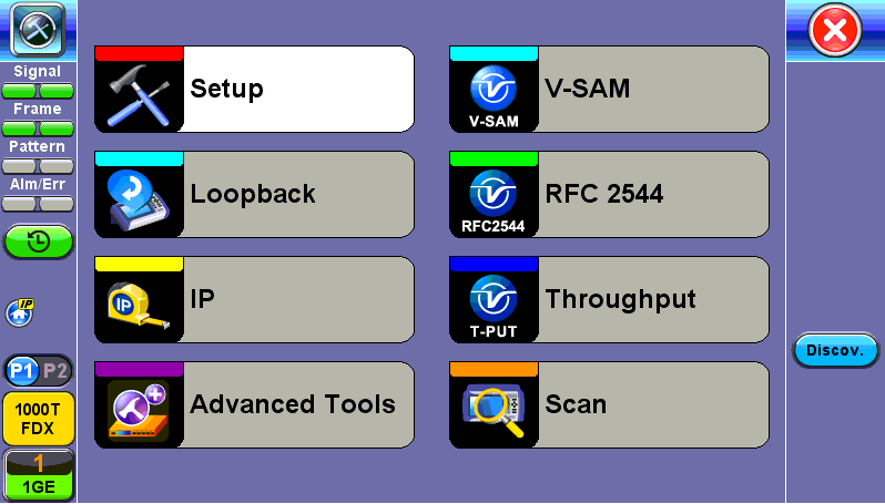
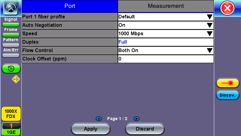
Port (Test Port selection)
Prior to starting the SyncE operation, the selected test port must be connected to a network that supports SyncE timing synchronization. Port selections include 100/1000T and 100/1000BaseX. After setting up the port, IP connection is not required for SyncE tests. Please see section Port Setup for port configuration instructions.
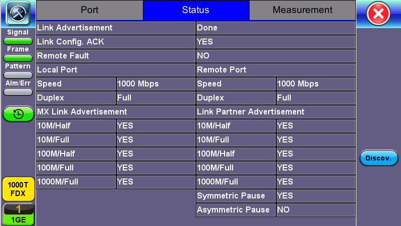
Port Status
Port Page 2 - Mode Selection
Master and Slave Mode
Master Mode emulates a SyncE Master clock device and slave mode emulates a SyncE Slave clock device. Both modes operate out of the Ethernet test port (100/1000BaseT, 100/1000BaseX, or 10GE) and can use an internal or external reference clock.
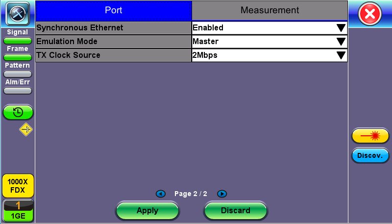
SyncE Master-Emulation Mode
- Synchronous Ethernet: Enabled or Disabled.
- Emulation Mode: Select Master or Slave emulation mode. In Master mode, the unit uses the TX Clock Source reference clock to provide SyncE clock on the Ethernet interface (10/100/1000T and 100/1000BaseX or 10GE port). In Slave mode, the unit recovers SyncE clock from the Ethernet interface (10/100/1000T and 100/1000BaseX or 10GE port).
- TX Clock Source (Master Mode): Select between an internal or external clock source. This clock is used as a reference clock for SyncE Master operation.
- Measurement Clock Reference (Slave Mode): Select between an internal or external clock source. This clock is used as a reference clock for SyncE Master and for SyncE Slave Wander Measurement.
Possible Internal Clock sources: Internal Clock (+/-3.5ppm accuracy), Internal GPS 1 PPS (Requires GPS option and Antenna), Internal Atomic 1 PPS (Requires High Precision Atomic Clock option). - Possible external clock sources: 1.5444MHz,1.544Mbps, 2 MHz, 2Mbps (E1 signal), 10MHz, 25MHz, 125MHz or External1 pps. The external clock source is connected to the SMA port on each Test Module. This port is marked CLK on the connector panel.
 Avoid using rigid BNC-to-SMA adapters to prevent any stress on the test set’s connector. Flexible adapters or cables are recommended.
 - Recovered Clock Output: The reference clock used by the SyncE master or slave can be regenerated out of the PDH TX port (marked Tx on the connector panel) with a different clock format in order to synchronize other network elements. In Slave mode the Reference Clock Output is the regenerated clock recovered by the SyncE slave.
The clock can be formatted to: 2Mbps (E1 signal), 2MHz, 10MHz, 25MHz, 125MHz, 1PPS and None. - If 2Mbps clock is selected from Recovered Clock Output, then the following parameters need to be set:
- Line Code: HDB3 or AMI
- Framing: Unframed, PCM31, PCM31C, PCM30, or PCM30C
- PRBS Pattern
- Invert
- Offset(ns) (only for 1 PPS Recovered Clock Output)
Press Apply once all the parameters are set.
Status
Status
Indicator Symbols
An M or S indicates that the test set is in Master or Slave Mode. A green icon indicates a successful Slave to Master connection. If the icon is solid red, there may be an issue with setup and the test will not work.
| Symbol | Description |
|
|
Test set is in Master mode. |
|
|
Test set is in Slave mode. |
Master and Slave Clock IDs get populated once the test is started.